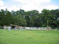
 A...
A...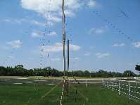 B...
B...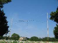 C...
C... D...
D...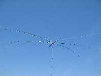 E...
E...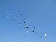 F...
F...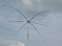 G...
G...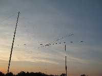 H
H
After doing field day last years at my sister's house, I came away with the idea to use an antenna with some gain on 40 meters. Out of that initial idea and with a year to think about it, I decided to try a multiband Moxon Rectangle using fiberglass poles. The antenna needed to be rotatable and light so I could use the masts from Field Day 2003. Photos A and B show the masts setup procedure with the 4x4 gin pole and boat winch. Photos C through H show the Moxon in place.
In order to change bands the antenna was lowered, and another element loop was connected in place of the previous loop. Multiple loops are possible on a Moxon, but not without a lot of tweaking. To avoid complexity, the loops for the various bands were arranged concentrically beneath the antenna on the ground with the highest frequency element being in the center. Photo A shows Cliff lowering the antenna with the same winch that was used for erecting the masts. Pictures B and C show the antenna in the lowered position. Picture B shows the small TV rotator and the trolley for centering the antenna between the masts. Photo D is the Balun, photo E is the center insulator , and photo F is the end insulator of which there are two. Picture G shows how the element loop is connected to the fiberglass structure. A small loop of rope is hose clamped at the four appropriate positions for each band onto the fiberglass poles. A plastic chain link was cut and tie wrapped into the corners of the element loop. To change bands, we just had to lower the antenna, unhook one element loop, and hook another.
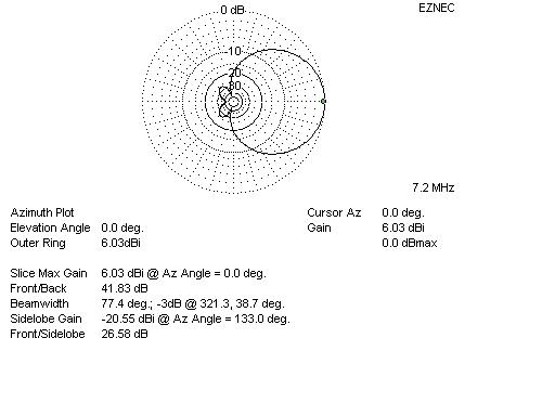
The Moxon antenna was first conceived by Fred Caton, VK2ABQ, as a square and later modified into a rectangle by Les Moxon, G6XN. L. B. Cebik, W4RNL, later refined it into the antenna dimensions that we used. A more detailed summary of the Moxon was written by Cebik. A Moxon generator is available which will calculate all the dimensions and even produce an EZNEC file for analysis. A typical free space pattern for the Moxons shown in picture A is shown in picture B below. Since the free space gain of a dipole is 2.16 dbi, the Moxon has 3.87 db gain over the dipole and the front/back ratio of 41 db is phenomenal. At 40 feet, over an average ground, with copper losses, the 20 meter Moxon is shown in photos C and D as compared to a dipole shown in E and F. You can see that a 3.16 db gain and 18 db front-to-back ratio can be obtained even at these low heights.
A...
 B...
B...C...
D...
E...
F
However, the proof is in the operation. Shown below in photos A and B are Cliff and Joe at the operating position in the barn. We made 647 contacts on 80, 40, 20 and 15 meters. At one point the logging program that we used showed that we were working predominately east coast stations. When we rotated the Moxon to the west about all we worked were west coast stations. The front-to-back really was working. The logs are : 80 m ssb, 40 m ssb, 20 m ssb, and 15 m ssb. Joe (N0KTA) also has posted some nice pictures. They can be accessed by clicking here.