 A...
A...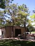 B...
B...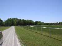 C...
C...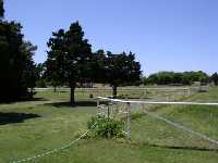 D...
D...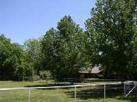 E...
E...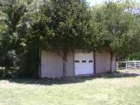 F...
F...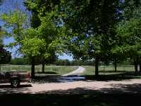 G
G
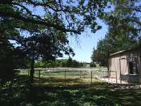
Hayes and I decided to do Field Day this year in Oklahoma. My sister and her husband have about 40 acres of land which are just begging for some good antennas. Hayes drives close to their place on his way from Kansas to Oklahoma...a trip he makes often, so he stopped by to get the lay of the land. Hayes took pictures A through G. As you can see, there are plenty of trees, but since Hayes and I decided to run two double extended Zepps perpendicular to each other, we will use the trees for shade and support our Zepps with masts. Using Roy Lewallen's (W7EL) EZNEC antenna software, I found that we could get good high angle performance and matchable impedances on all bands (80 meters through 10 meters), if we supported the Zepps at 30 feet from the ground and fed them with 100 feet of 450 ohm ladder line.
A simple mast can be constructed from three 2 X 4's, and they are inexpensive. Since the masts must be constructed in Oklahoma at the last minute, I decided to do a dry run on the construction so there wouldn't be any surprises. Pictures A through H show the results of the dry run and the details of the mast construction.
Hayes and I are planning on running a Yaesu FT-857 and an Icom 706. Both of these rigs are synthesized, so they radiate a small amount of broadband noise when they are keyed. Since this noise is on the level of 2 microwatts, it usually is not a problem. However, since both radios will be running in very close proximity to each other, the noise can be heard on the other radio as soon as the transmitting radio is keyed. The only band that does not have this problem will be the lowest band used, which is 80 meters for us. The lowpass filter is probably killing the noise on 80 meters. So I decided to build bandpass filters on 40, 20, and 15 and a highpass filter for 10. Pictures A through D show details of the filters. Pictures C and D show the inside of the 40 meter bandpass filter. The filter design calls for inductors ranging from 3.22 uH to 0.35 uH. Whenever it is possible, from a size and unloaded Q standpoint, it is better to use air coils rather than coils wound on a core. This filter uses a core only on the largest inductors, and the core is a T106-6 which is physically large and has a low permability to prvent saturation. This core has an unloaded Q of about 400 while the air inductors have an unloaded Q of about 300. The high unloaded Q is very important on bandpass filters to keep the insertion loss low. The table below shows the electrical results of the filters.
BAND
10 Meter HighPass 15 Meter BandPass
20 Meter BandPass 40 Meter BandPass
Attenuation (db) Attenuation
(db) Attenuation
(db) Attenuation
(db)
10
-0.3 (6 watts)
-28
-65
-60
15
-40
-0.7 (14 watts)
-36
-70
20
-40
-35
-0.6 (12 watts)
-48
40
-38
-65
-40
-0.1 (2 watts)
80
-40
-70
-50
-40
Note: The insertion loss is based on about 90 watts output from the transceiver.
All of the bandpass filters are 5-section Butterworth filters and the highpass filter is a 3 section elliptical. The values used were the calculated values except for the center shunt element on the 15 meter bandpass. The inductor was too low to realize a good insertion loss because of the strays, so I adjusted the LC ratio on this section to lower the insertion loss which widened the bandpass.
Back to the antennas...after running the 80 meter Double Extended Zepp through EZNEC, Hayes and I decided that the "pattern holes" on the higher bands would limit our geographical coverage, so the decision was made to change the antenna design to Inverted V's with jumpers on each side of the dipoles to change their resonant frequencies. In order to facilitate the band changes in the middle of the night, an Inverted V configuration was decided upon since only the middle of the dipole, rather than both ends, needs to be let down to change the jumpers. The idea is to use the 2 x 4's that we were going to use for 30 foot masts to build two 46 foot masts and four sixteen end supports for the two dipoles. If this works there will be more details on the construction of thes 46 foot masts because it will have to be tried in Oklahoma since time is running out. Pictures A through D show the details of the jumpered dipole. The dipole was designed using EZNEC. Each dipole covers 80 meters through 10 meters. The apex angle is 130 degrees with the center being 46 feet high and the ends being 19 feet high. Each section of the dipole was adjusted in length for resonance, and then the next section was added, and the process was repeated. The insulators are made of epoxy glass pc board material with the copper removed. Each insulator leaves a 2.4" gap when the jumper is removed. Since the added wire of the rest of the sections slightly effects the sections before, two length adjustment iterations were done to insure resonance. The final lengths are given below:
Band Calculated length
Dipole1 Side1 Dipole 1 Side 2
Dipole 2 Side1 Dipole 2 Side 2
10
8' 3 3/4"
8' 3 5/8"
8' 3 1/2"
8' 3 5/8"
8' 3 5/8"
15
11' 3 1/2"
11' 3 1/2"
11' 3 5/8"
11' 3 3/8"
11' 3 3/8"
20
16' 10"
16' 9 7/8"
16' 10 1/8"
16' 10"
16' 10"
40
33' 3 1/2"
33' 3 1/2"
33' 3 3/4"
33' 3 3/8"
33' 3 3/8"
80
62' 3 1/2"
62' 3 1/2"
62' 3 3/4"
62' 3 3/8"
62' 3 1/2"
Dipole 1 will be oriented broadside to a true heading of 50 degees. On 10, 15 and 20 meters, the main lobe will cover the heavily populated areas from Wisconsin to the DC area. Dipole 2 will be oriented broadside to a heading of 285 degrees true to cover the heavily populated area of California on one side and Florida on the other side. On the lower bands of 80 and 40 the pattern is more omnidirectional due to the low height of the antennas which will give good coverage into the midwest and Texas.
Theory is nice, but I wanted to give the antenna an actual test, so I erected 30 feet of mast in the back yard and tested the 40 meter through 10 meter sections of one of the dipoles. I did not test the 80 meter section, because my yard is too small. Picture A shows the dipole and mast. If you look closely on the left side, you can see the insulators with the jumpers. Pictures B and C show the transceiver set up, and picture D shows the choke balun that was installed at the antenna feedpoint. This balun just consists of 14 turns od RG-58 coax wound on an FT240-43 core. The results were good in that all antennas resonated in the band with the 2:1 SWR points listed below:
Band
Low 2:1 SWR Frequency
High 2:1 SWR Frequency
Minimum SWR Frequency of
Minimum SWR
10
27.7
29.8
1.2:1
28.7
15
20.97
22.0
1.3:1
21.5
20
13.9
14.67
1.4:1
14.13, 14.45 *
40
6.84
7.23
1.1:1
7.02
* There were two minimum SWR points on 20 meters.
I expect these numbers to be slightly different when the antennas are erected in their final configuration in Oklahoma.
All of the plans have been made, and it is time to start packing for the plane trip to Oklahoma. A call to the TSA at Denver airport directed me to their web site for the dos and don'ts of carry on and checked baggage. None of the things that I am packing fall into either list, so I call TSA again and explain what I plan on taking. They don't think it will be a problem, but they explain it is always up to the agent at the security check, so I try to use a little common sense. I'll carry on everything that is absolutely necessary and check the rest, making sure to have no sharp objects in the carry on. So one carry on consists of the transceiver, instruction manuals, power supply, speaker, telegraph keys, microphone, boom mic with headphone, filters, computer, coax connectors, and antennas. The other carry on has a watt meter, antenna analyser, voltmeter, and headphones. Pictures A, B, and C show the contents of these two bags. The checked bags have 1000 feet of wire, 1000 feet of rope, tools, brackets, guy anchors, a power strip, and an antenna tuner, and , oh yes, some clothes. The contents of these two checked bags are shown i pictures D and E.
Believe it or not, all of these bags went through security without being opened. I don't know whether this means the system works extremely well or it does not work well, but in either case, it was a no hassel trip for me. All of the equipment arrived in perfect condition. The lumber for the masts were waiting for me in the barn thanks to my brother-in-law and his son-in-law. Pictures A through D show some of the mast construction. The masts stand 44 feet tall and are constructed from three 2x4's and a 4x4. The gin pole is constructed from three 2x4's and a small boat winch.
Of course Gretta and Mag shown respectively in photos A and B had to help.
The antennas will be erected in the arena just outside of the barn. The horses were moved to another pasture so they would not rub up against the masts. Pictures A and B show this area.
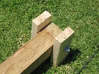
The idea is to fasten the mast to a pivot point and pull it up with the gin pole. A shows the pivot, and B shows the mast ready for erection. Picture C is the gin pole and pictures D through K show the mast being pulled up. Pictures L, M, and N show Hayes, Zac, and Tom adjusting the mast for vertical.
 A...
A...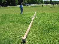 B...
B...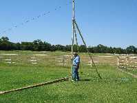 C...
C...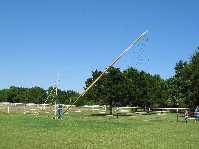 D...
D...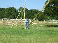 E...
E...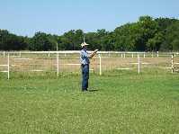 F...
F...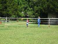 G...
G...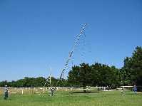 H...
H...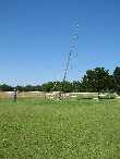 I...
I...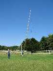 J...
J...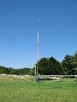 K...
K...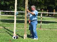 L...
L...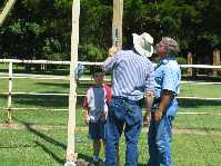 M...
M...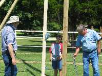 N
N
After the mast had been adjusted for vertical the bottom braces, which consisted of four eight foot 2x4's were installed. Picture A shows the pivot in the vertical position, and B and C show the bottom braces. Picture D shows the mast completed.
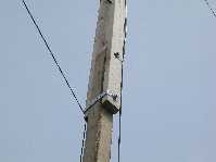
Picture A shows the junction brackets. Pictures B and C show the guy anchors which were 12 inch nails. D and E show the antenna installed. F and G show the two masts erected. Picture H shows one of the end poles of the inverted V dipoles which is a 16 foot 2x4 situated so that the ends of the dipoles were at about 19 feet which gives a 120 degree angle at the apex. Photo I shows the gin pole in the down position.
 A...
A...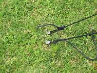 B...
B...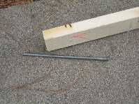 C...
C...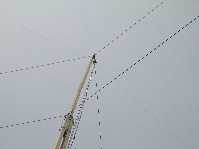 D...
D... E...
E...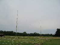 F...
F...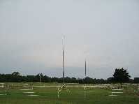 G...
G...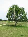 H...
H...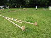 I
I
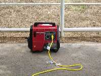
Hayes brought a nice 1 kw Honda generator for power shown in picture A. Pictures B, C, and D show the two operating positions with an Icom 706 and a Yaesu FT-857. Pictures E through N show the actual operation during the contest. Finally picture O shows that the masts stand very steadily without guys in a no wind condition.
 A...
A...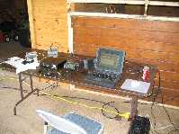 B...
B...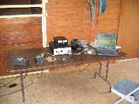 C...
C...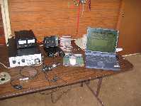 D...
D...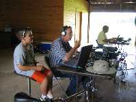 E...
E...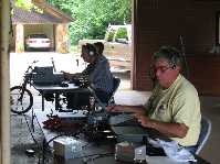 F...
F...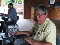 G...
G...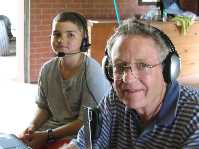 H...
H...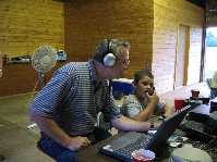 I...
I...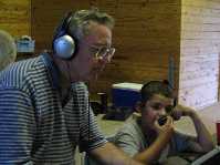 J...
J...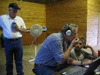 K...
K...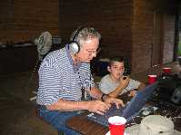 L...
L...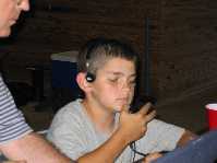 M...
M... N...
N...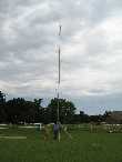 O
O
Over all, the field day was a success. We only made 422 contacts, but we all had a good time, and we may have recruited a new ham in Zac, the junior op shown above.