 A...HiRes ..
 B...HiRes..
 C...HiRes..
 D...HiRes
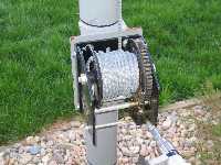
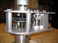
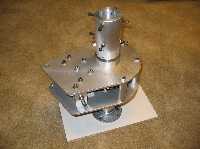
The design is based on sandwiching the gears and gear supports between two 5/16 inch 6061 T-6 aluminum plates as shown in Fig. B, Fig. C, and Fig. D. A 1 1/4 inch steel shaft was used and turned down to 1 inch in the middle to go through the hollow winch shaft. The winch drum was sawed off with a hacksaw and the hollow winch shaft was drilled out in order to accommodate the 1 inch steel shaft. The steel shaft was turned down to 3/4 inch on the bottom end in order to fit into a 3/4 inch steel tapered-roller bearing (part # 5709K13 and 5709K53 from McMaster-Carr). The top bearing is a double shielded ball bearing assembly and is part # 60355K821. These bearings and the turned down shaft may viewed in Fig. H.
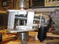
The motor to drive the rotator is a windshield wiper motor for a Ford F-150 truck. This motor rotates at about 60 rpm and has about 50 in-lbs of torque. The motor torque was measured dynamically by constructing a motor pulley with a 2 inch radius. Strong string was wrapped around the pulley and tied to a 25 lb weight which was lifted when the motor was energized. This motor yields a 1 rpm antenna rotation at about 2500 in-lbs of torque since the worm ratio is 51:1. The braking torque is hard to determine since a worm gear is basically self braking, but the braking torque is probably in excess of 10,000 in-lbs.
Fig. E shows the motor mounted with a homemade flexible coupler. Fig. F shows a 20K, 10-turn pot coupled onto the main worm gear with a homemade gear made with Delrin. This gear was sawed out with a band saw. It is pretty crude, but a precision gear is not needed in this application. This pot is used for position information. It will allow 705 degrees of rotation of the main shaft. Fig. G shows the completed rotator with the cowling in place. The cowling is made from a piece of 0.032 aluminum used for making aluminum gutters.
Fig. H shows most of the parts. All structural bolts and pins are grade 8 or higher. The pylons that hold the worm are capable of resisting 5000 lbs. This force was based upon the 10,000 in-lbs of braking torque desired.
 A...HiRes ..
 B...HiRes..
 C...HiRes..
 D...HiRes
 E..HiRes...
F..HiRes...
G..HiRes...
H..HiRes
Fig. I through Fig. K show the controller. The rotator rotation can be centered around either North or South depending upon a jumper on the control board. Fig. J shows what the diplay looks like for a North center, and Fig. K shows a South center configuration. The rotator is alowed to rotate 540 degrees, which leaves about 83 degrees of leeway on each end of the pot. When the Target Control is turned, the target position is shown on the display. When the ROT button is pushed, the controller figures out the shortest distance from where the rotator is actually pointing to the new position. The motor then tracks to the target position using a ramp up start and a ramp down stop to protect the antenna from large accelerations. The shortest distance is not always the apparent shortest distance because the controller will not allow the rotator to go too far in either direction in order to prevent wrapping the coax around the mast. If for some reason the motor stalls and draws excessive current, the controller stops the motor and flags a fault on the display.
The schematic of the controller is shown in Fig.L, and the block diagram of the controller is found in Fig. M. The controller uses a BX-24 processor made by NetMedia. The display is a 20 x 4 LCD module. The source code is writen in Basic and can be found here.
Figure N contains all the mechanical calculations for the rotator.
In summary, the rotator operates at 1 rpm and provides 2550 in-lbs of rotating
torque and 10125 in-lbs of breaking torque.
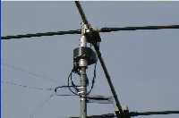
Figure O shows the rotator installed.
I..HiRes...
J..HiRes...
K..HiRes...
L
M....... ..
N......
 O...
O... ....YouTube
Video....
....YouTube
Video........YouTube
Video.....
Larry Benko, W0QE, machined many of the precision parts in this rotator
and made many helpful suggestions along the way. With out his help,
this project could not have been completed.
Also, I had many helpful hints from others in the Boulder area and
some of my friends on the air.