 A...
A...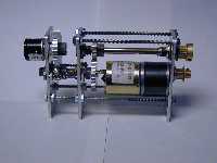 B...
B...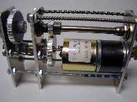 C...
C...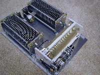 D...
D... E
E
 A...
A...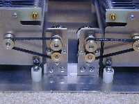 B...
B...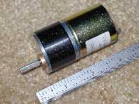 C...
C...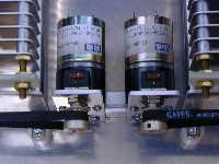 D
D
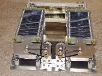
The automatic antenna tuner described here is the first part of automating my station so I can run it remotely. The tuner is a T-network, high pass tuner with variable capacitors in the series legs and a roller inductor in the shunt leg. Since the tuner will be automatically tuned, the capacitors and inductor are controlled with motors. The control of these elements will be done by a small microprocessor running Basic. This microprocessor is capable of floating point math, so I will actually calculate SWR using a forward/reflected power bridge and adjust the tuning elements for minimum SWR. Picture A shows the basic tuner components with the motors mounted on the capacitors. Each motor has a potentiometer in the drive train using small timing pulleys and belts so the position of the capacitor may be determined. Picture B is a close up of the drive train for the capacitors. Picture C is the motor and gear box which turns at about 17 rpm. Picture D is a close up of the motors and potentiometers.
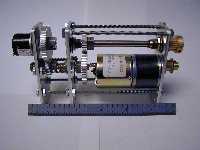
Since the capacitors only rotate a half turn, a single turn pot coupled to the shaft can be used to track the capacitor position. The roller inductor position cannot be tracked in the same manner since it rotates 40 times from end to end. A gear train coupled to a 10-turn pot was built and is shown in pictures A, B, and C. Since 40 turns are necessary, the gear train needs a reduction factor of at least four. A single gear pair design required the large gear to be almost 3 inches in diameter, so a two stage reduction scheme was used. The fine toothed, spur gears are 48 pitch gears with 30 teeth on the small gear and 64 teeth on the large gear which give a reduction of 2.13 per pair and a total reduction of 4.27. This train coupled with the 10-turn put gives a tracking range of 42.7 turns which is adequate for the 40-turn roller inductor. Pictures D and E show the gear train mounted and linked to the roller inductor.
The gear train in photos A, B, C, and E above did not work well because the timing belt did not have enough contact with the timing pulley to prevent slippage during parts of the roller inductor travel. Photos A, B, and C show the redesign of the gear train for the inductor.
In the process of developing the software for this automatic tuner, I realized that I really needed to understand the highpass, T-network tuner better. As a result I wrote two Basic programs. One program synthesizes a highpass, T-network tuner given the impedance at the the output of the tuner. It can be downloaded and run under DOS. The executable is Tnetcalc.exe and the source code is Tnetcalc.txt. The other program analyzes a highpass, T-network tuner and gives the impedance that is being matched by inputting the values of the three elements of the tuner Ci, the serial arm input capacitor, L, the shunt inductor, and Co the serial arm output capacitor. The executable is Tuner.exe and the Basic source code is Tuner.txt. This program will actually be a part of the antenna tuner. When the tuner yields an SWR of exactly 1:1, the input of the tuner is exactly 50 ohms resistive. I plan to fit a curve to each element of the tuner, so that reading the pot on each element will allow me to calculate the capacitance or inductance of the particular element. The impedance that is being matched can then be calculated along with the circuit Q and tuner losses. Since the BasicX-24 microprocessor that will control the tuner has floating point math, these calculations are easy. Since the BasicX-24 uses a very similar Basic to Quick Basic, which the tuner routines are written in, transporting the Tuner.txt code to the BasicX-24 code took less than an hour. The complete tuner analysis in the BasicX-24 chip takes less than 70 milliseconds which is not too bad considering that math functions such as Cosines, Sines, Logs, Square Roots, and Exponentials are used. If you want to try these programs, download the two executables and use Tnetcalc.exe to design a tuner and then feed the three tuner elements along with the input resistance and frequency into Tuner.exe and get the matching impedance back.
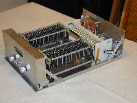
Below, photos A through H show the tuner construction to date. Picture I is a mock up of how the display might look. Photos J, K, and L show the circuit board on the rear panel that does the antenna switching and the serial port switching. Pictures M, N, and O show the little sub-board that does the serial switching. The microprocessor will be programed through the same port that it communicates with the tranceiver, amplifier. and remote unit. The microprocessor is programed via RS-232 and communicates with other devices via an RS-485 bus, so the serial port must be switched between RS-232 and RS-485.
 A...
A...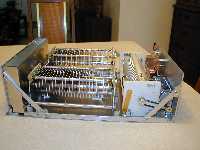 B...
B...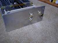 C...
C...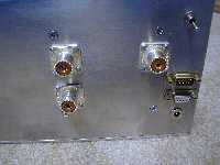 D...
D...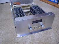 E...
E...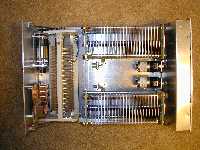 F...
F...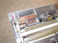 G...
G...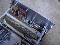 H...
H...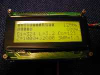 I...
I...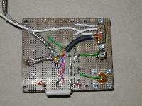 J...
J...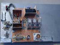 K...
K...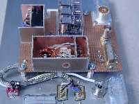 L...
L...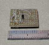 M...
M...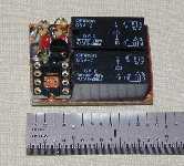 N...
N...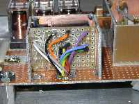 0
0
Unfortunately, I never finished this Project!