 A...
A...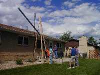 B...
B...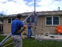 C...
C...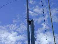 D...
D...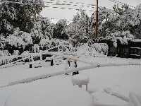 E...
E...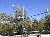 F...
F...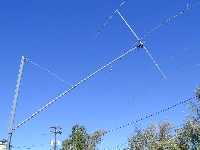 G...
G...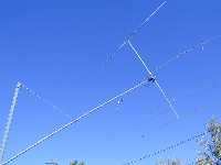 H...
H...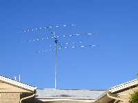 I...
I...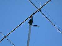 J...
J... K...
K...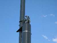 L...
L...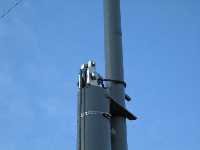 M...
M... N...
N...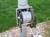 O...
O...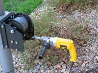 P...
P...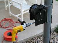 Q
Q
It seems as if our society is becoming more and more conscious of aesthetics in neighborhoods. This does not bode well for ham antennas. However, an antenna can look good and still be effective and strong in the wind. We have very high winds in my area on occasion, so this antenna was designed to withstand 110 mph with no guy wires and no industrial looking structure. Here is a pictorial story of the erection of a 40 foot, self-supporting, fold-over tower.
 A...
A... B...
B... C...
C... D...
D... E...
E... F...
F... G...
G... H...
H... I...
I... J...
J... K...
K... L...
L... M...
M... N...
N... O...
O... P...
P... Q
Q
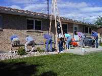
Picture A shows a group effort to position the 24 foot bottom pole for erection. This 4.5 inch OD 1/4 inch wall steel pole weighed about 300 pounds. It is 55,000 psi steel drill pipe. Picture B shows the pole being lifted using a homemade derrick made from 16 foot 2x4s. The tower winch was temporarily mounted on the derrick. The pole was set into an 8 inch casing that had previously been set in concrete in a 3 foot by 3 foot by 4 foot deep hole. After setting the bottom pole into the casing, the pole was plumbed and sharp sand was poured in around it. The sand acts as a shock absorber for the concrete and holds the pole perfectly straight. Roofing tar was put on top of the sand for the last 2 inches to keep the sand dry. The winch was then moved from the derrick to the bottom pole. Before the bottom pole was erected, the 5/16 inch winch line was placed in position on the pulley mounted on top of the bottom pole. The 30 foot top pole which is a 2 7/8 OD steel pipe with a 1/4 inch wall, was drawn up into position using the winch and pinned at its hinge. The top pole weighs about 175 pounds and is also built from 55,000 psi drill pipe. Picture C shows this process. After pinning the bottom pole, the winch line was moved up the pole into position and the top pole was winched up into its cradle as shown in picture D. The winch is a Fulton KW3000 winch which has been replaced with a Fulton KW30000103. It has a worm gear which will hold tension on the cable which holds the top pole in its erect position in its cradle. So far this does not rattle, even in strong winds.
Finally, in early fall, I assembled the antenna, an A4S with a 40 meter kit, in the back yard, and was looking forward to attaching it to the tower the next day. No good antenna project can be done in good weather, and this was no exception. Picture E was what greeted me early the next morning. However, being the optimist that I am, I cleared the snow from the antenna, shoveled a little beneath the antenna, and let old Sol do his job. By noon the snow had melted some, so I stood the antenna up against the bushes, lowered the tower into position, and placed the antenna onto the mast as shown in picture F. Finally pictures G and H show the antenna as it is being winched up and picture I shows the antenna in the full upright position. Picture J and K show details of the rotator and the current baluns on the yagi and the 80 meter dipole. Pictures L, M, and N show the pulley and the caging mechanism used to keep the line on the pulley dueing slack line conditions. In the first design, I did not have the caginging mechanism (notice picture D), and the line jumped off the pulley causing a very fast fold down of the tower and some damage to the antenna. Pictures O, P, and Q show the winch and an 850 rpm, 7.5 Amp drill motor for driving the winch. The antenna can be winched either up or down in about 8 minutes by hand leaving the cranker quite aerobic. The drill motor cuts the winching time to about 3 minutes, and it is considerably easier. With a small step ladder, the driven element may be reached easily since the boom is only 18 feet long. By rotating the beam before fold down, the reflector or director will be on the ground for easy access. So far, the winds in the area have been clocked at 90 mph, and although the antenna and the top of the tower move around, they have withstood the winds well.
Alas, the Boulder winds broke the A4s, so in March of 2004 I became
the proud owner of a FluidMotion's
SteppIR 3 element yagi. Pictures A
through D show this installation.
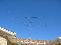 A...
A...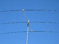 B...
B...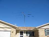 C...
C...D
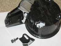
Well, I had the new SteppIR up about 2 weeks when we got a wind that gusted to 78 mph. I was awakened by the wind so I retracted the elements on the SteppIR so the elements would not be damaged if I lost a fiberglass elemrnt housing. About 6:30 in the morning the wind was still up to 60 mph when I checked the antenna. Much to my dismay, the whole antenna was dangling by the feed line and being tossed by the wind. I quickly cranked the fold over tower down even in the high winds. Normally the antenna will clear the bushes at the edge of the lot, but with it in this condition, it quickly became tangled in the bushes. At least the bushes stabilized the antenna from the wind tossing. Since the elements were retracted, I continued to lower the tower as I removed each fiberglass element housing. At this point I discovered what had gone wrong. The rotator housing had broken! Since the rotator was pole mounted instead of being caged by a tower, I was aware that the stress on the rotator was more than a caged rotator. The specifications for my rotator only go up to 67 mph, and I was below the stress level at those speeds, but evidently not enough at my wind speeds. In any case, after talking to the technical support people, I decided to cage the rotator in order to transfer the lateral stress to the pole.
Picture A shows the broken rotator housing
and bracket. Photos B through F show the cage that
I constructed for protecting the rotator. Hopefully this modification
will enable my antenna to withstand the Boulder weather.
 A...
A...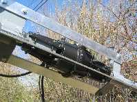 B...
B...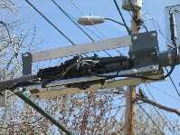 C...
C...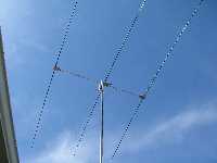 D...
D...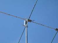 E...
E...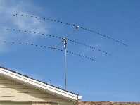 F
F
Summary:
The Tower Project has had two design faults, both which
have been corrected.
1) I failed to put a keeper on the top of the pulley, so the cable jumped the pulley when there was no tension on the cable. This was corrected as shown below.
2) I also failed to to wrap the cable multiple times around the top pole as is shown above, so the cable clamps worked loose. This was corrected as shown below.
Also, The commercial rotator that I chose has not been up to the high winds that we have each winter here in Boulder. I have since designed my own rotator as shown below. It seems to be working well. Details of this project can be viewed by clicking here.
The antenna project continues. For aesthetics, I ran all my control and feed lines up the center of the tower. In order to get them out the top, I cut a slot in the short piece of pipe right under the rotator. In the fall of 2015 we had close to 100 mph winds in Boulder. We woke up to sound of something banging on the roof. I went outside to discover my 3 element SteppIR and rotator dangling from the top of the tower. The pipe with the slot had broken due to its mechanical integrity being compromised by the slot. Photos A and B below shows this. I replaced the short schedule 40 pipe with a schedule 80 pipe and ran my control and feed lines up some pvc pipe attached to the tower as shown in Photo C below.
When I let the tower down for repairs, I noticed thatthebering in the winch had worn out as shown in Photo C below. I replaced the winch with a Thern Model 4771, 120 V powered winch of much higher quality as shown in Photos D and E. Photo F shows the nice control switch and Photo G shows a temporary weather protection bag.
INTERESTING: My
Friend, Allen K0ARK, Took the above HTML file and used Google Gemini Advanced
to create a podcast using artificial intelligence. Click HERE
to hear the podcast.