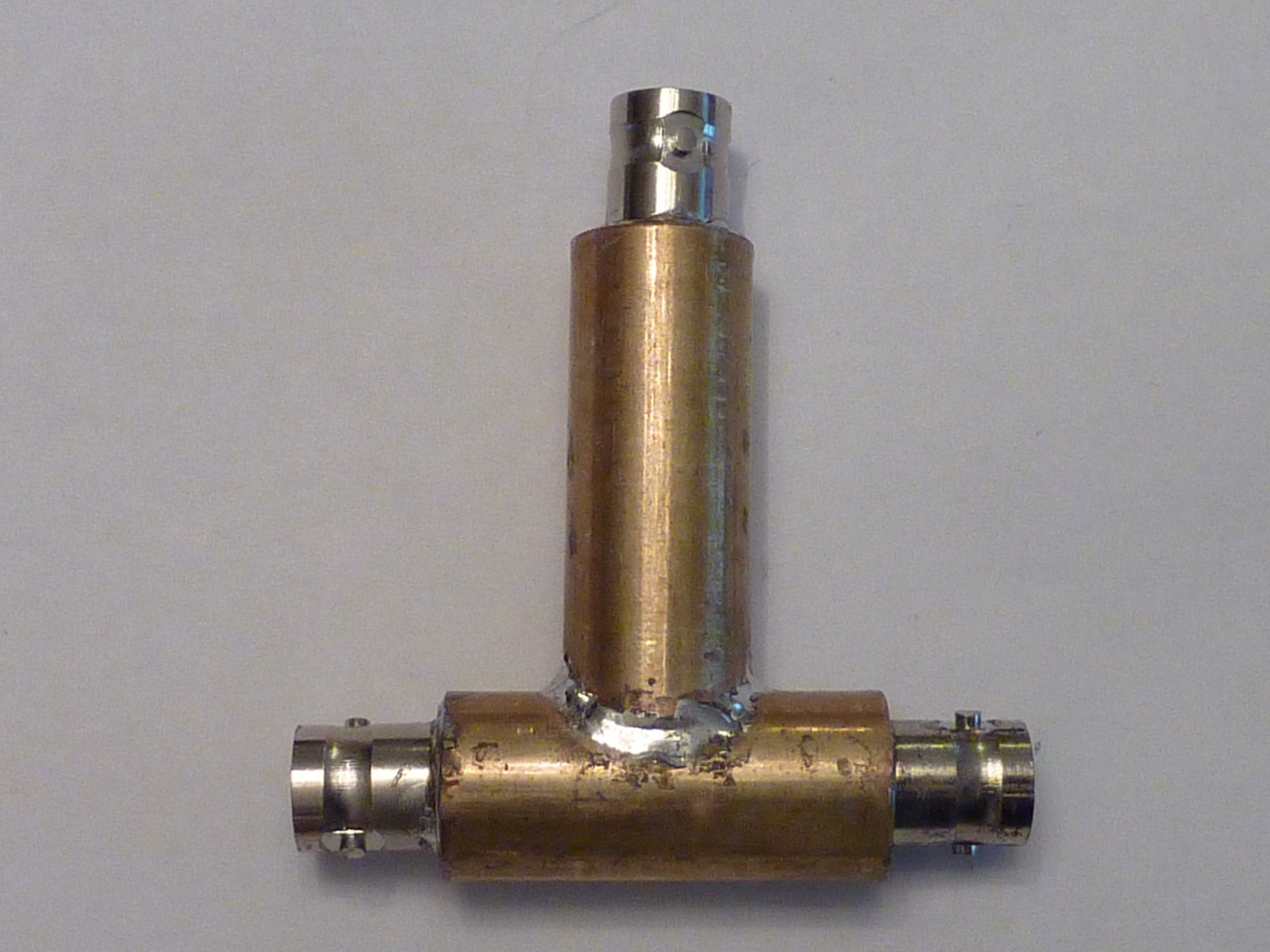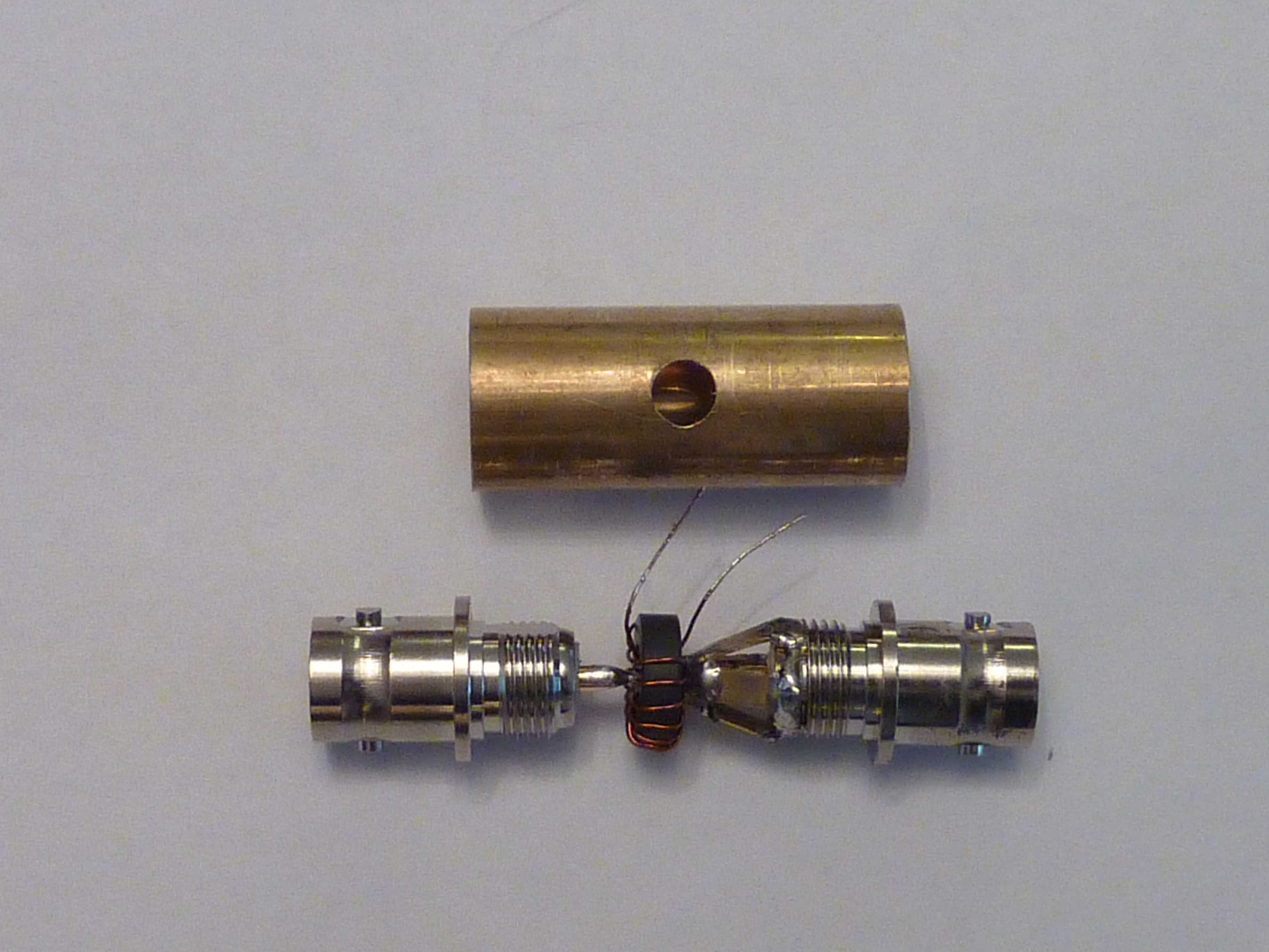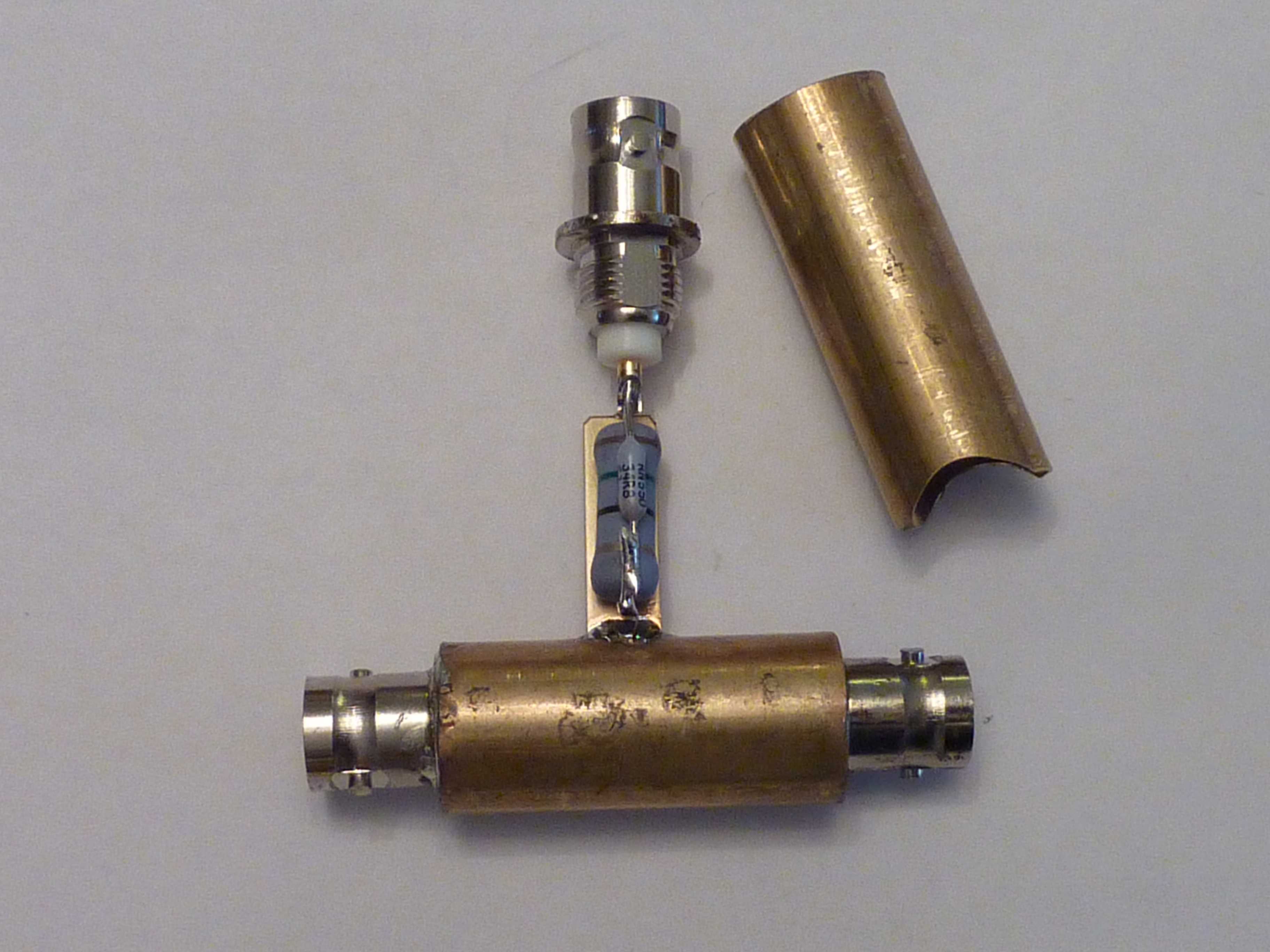
This is an RF Sampler using a toroid transformer.
The advantages of this type sampler are:
1) Simplicity
2) All ports provide a 50 Ohm
impedance.
3) This sampler offers very
little attenuation to the transmitted signal and will handle 1500 watts.
There are two different samplers described here.
Each sampler provides a 40-dB atenuated RF signal out the sample port.
They are shown below.

Tube type sampler.


Tube sampler open.
This sampler is harder to build than the box type shown
below.
Box Sampler with 3 pF compensation capacitors. The compensation capacitors extend the frequency range beyond HF.
Details of the Sampler Schematic and Calculations are shown below:
Sampler Schematic and Calculations.
The core size needs to be large enough to accomodate the coax size.. The core may be an FT43 or FT61. I used an FT37-61 core with 15 turns of #28 enamel wire on my samplers and smi-rigid coax. The 15-ohm resistor is a 2 watt, film resistor and the 35-ohm resistor is a 1/4 watt resistor.
Test results of the two samplers are shown below.
Both the Tube sampler and the Box sampler have similar SWR curves through
the sampler, but the Tube sampler is slightly better than the Box sampler
in terms of attenuation. However, the Box sampler is probably
adequate for most amateur work at HF. Caution:
The shield of the coax should be grounded on only one end.
Through line SWR Curve.
Attenuation Data.