The radioberry tranceiver is a "HAT" that plugs into the Raspberry Pi 4 b computer. It provides both receive and transmit capability over the HF spectrum from 0 to 30 MHz. the specifications are shown below. The Radioberry requires software to operate. The software steps are listed below:The Radioberry HF Transceiver
Tom Thompson W0IVJ
The Radioberry needs software to operate. The steps are listed below:
1) Acquire a micro SD card (32 gB or 64 gB) for the Raspberry PiOS and download the imager: https://www.raspberrypi.com/software/
2) Install the imager and download the PiOS onto the SD card.
3) Set up the PiOS on the Raspberry Pi 4 b making the user name is PI.
4) At this point, operation is from the Raspberry Pi and an internet connection is necessary.
5) These instructions are from Mike O'Callahan NJ0L.
Radioberry and pihpsdr install.
Use the github Radioberry Wiki: https://github.com/pa3gsb/Radioberry-2.x/wiki
Choose RPI OS settings as instructed on the “Raspberry PI” page.
Follow instructions on “Radioberry configuration” page, using scripts found
via the “releases” link.
Choose the CL025 firmware option for the AURSINC radioberry version we
have.
Follow “releases” page instructions to install pihpsdr.
Install WDSP first, then pihpsdr using the software/script.
Answer “no” to the CW question.
Now run pihpsdr – choose “wlan0” in start options.
Should be running now!
Now that PiHPSDR is running on the Raspberry Pi 4b,
here is the Hardware.
Radioberry Specifications.
The Radioberry "HAT" on the RaspberryPi 4b is shown below. The Raspberry Pi measurements are: 3.4 x 2.2 inches. The Radioberry on the Raspberry Pi 4b is about 2 inches tall.
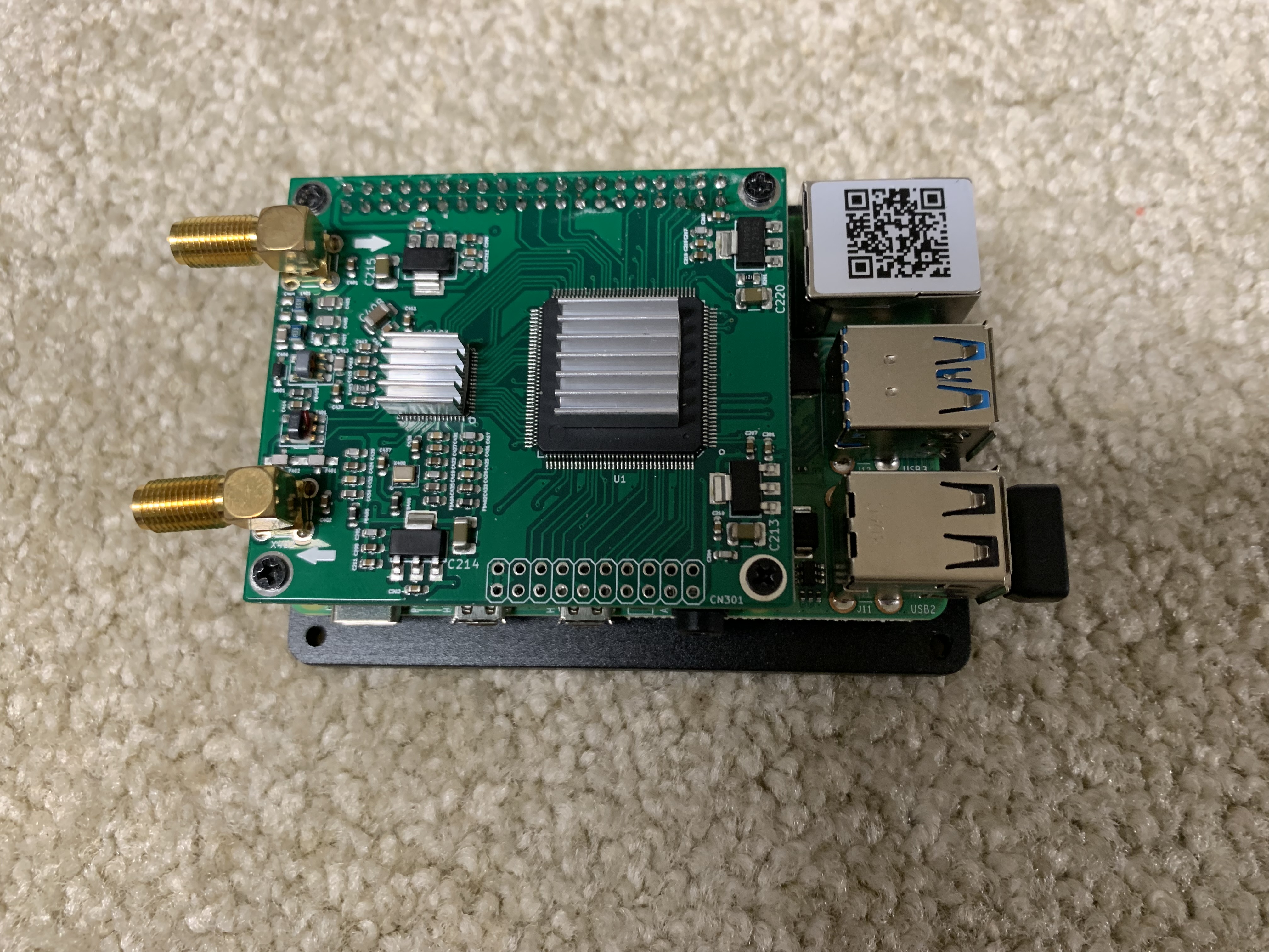
Radioberry and Raspberry Pi 4b.
My complete transceiver is shown below. The size is largely determined by the 10 inch, HDMI monitor for height and width, and the power supplies and power amplifier for depth. I, also, added several auilary boards which will be explained below..
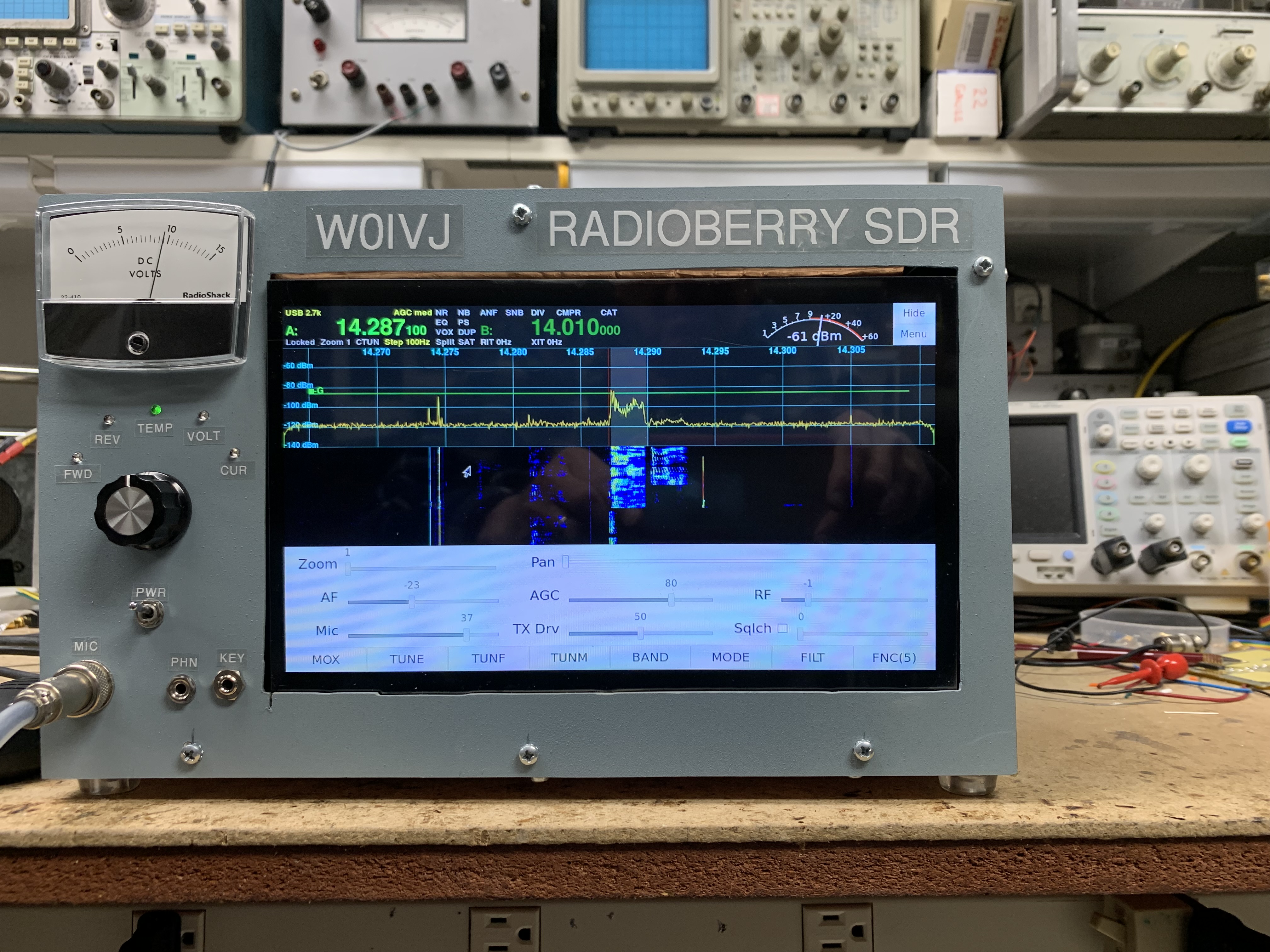
Complete Packaged Radioberry Transceiver.
The Block Diagram is shown below. Several additional circuits were added to the fundamental Radioberry. However, with the addition of an HDMI monitor and a mouse / keyboard, the Radioberry is a complete transceiver. A T/R relay is needed if the transceiver uses the same antenna for transmit and receive since the Radioberry has a transmit port and a receive port.
Transceiver Block Diagram.
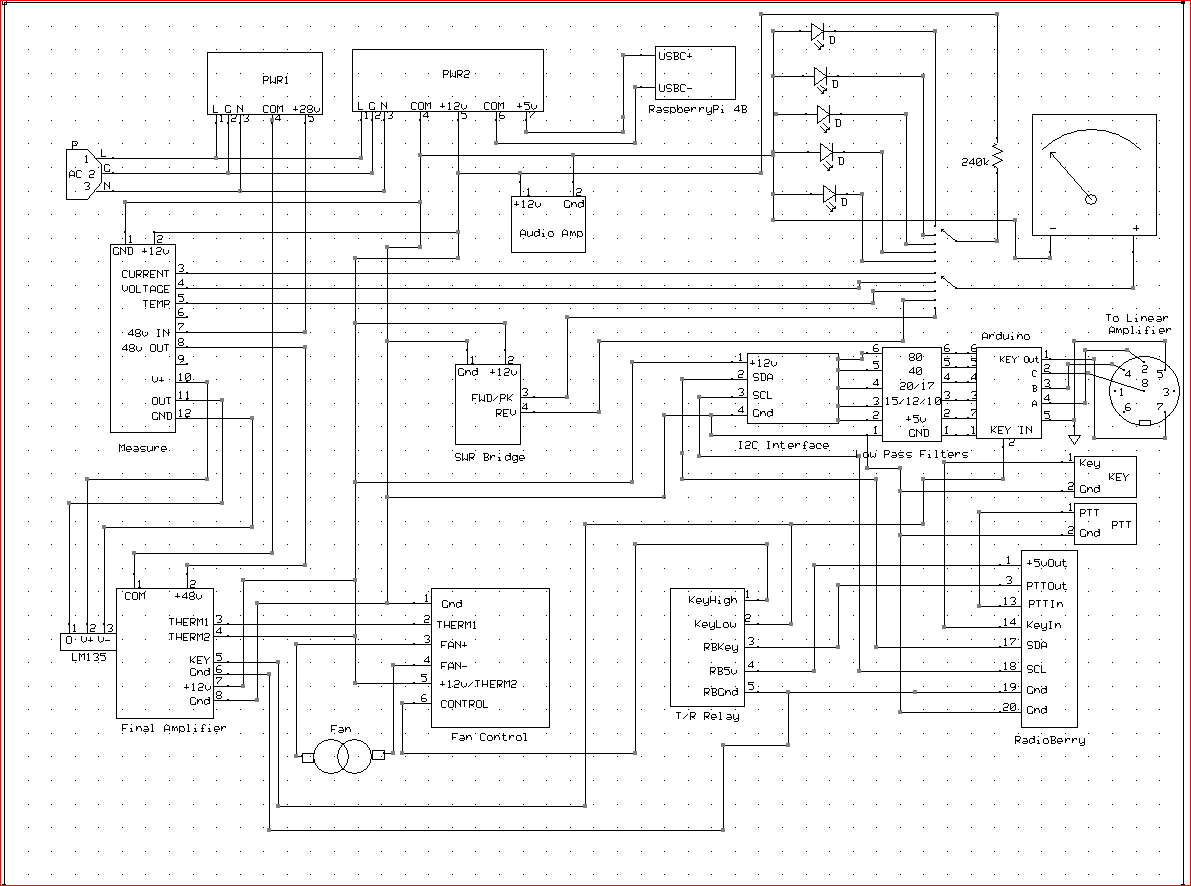
Wiring Diagram.
Here is a list of the home brew boards that were added
to make the transceiver:
1) Power Amplifier.
2) Proportional Fan Controler.
3) T /R Relay.
4) Audio Amplifier.
5) Parameter Measure Circuit.
6) Forward / Reflected Power Bridge.
7) Low Pass Filter Board.
8) I2C Filter Interface Board.
9) Arduino Interface for External
Linear Amplifier.
With all of those boards connected, the inside of the transceiver viewed from the top is shown below.
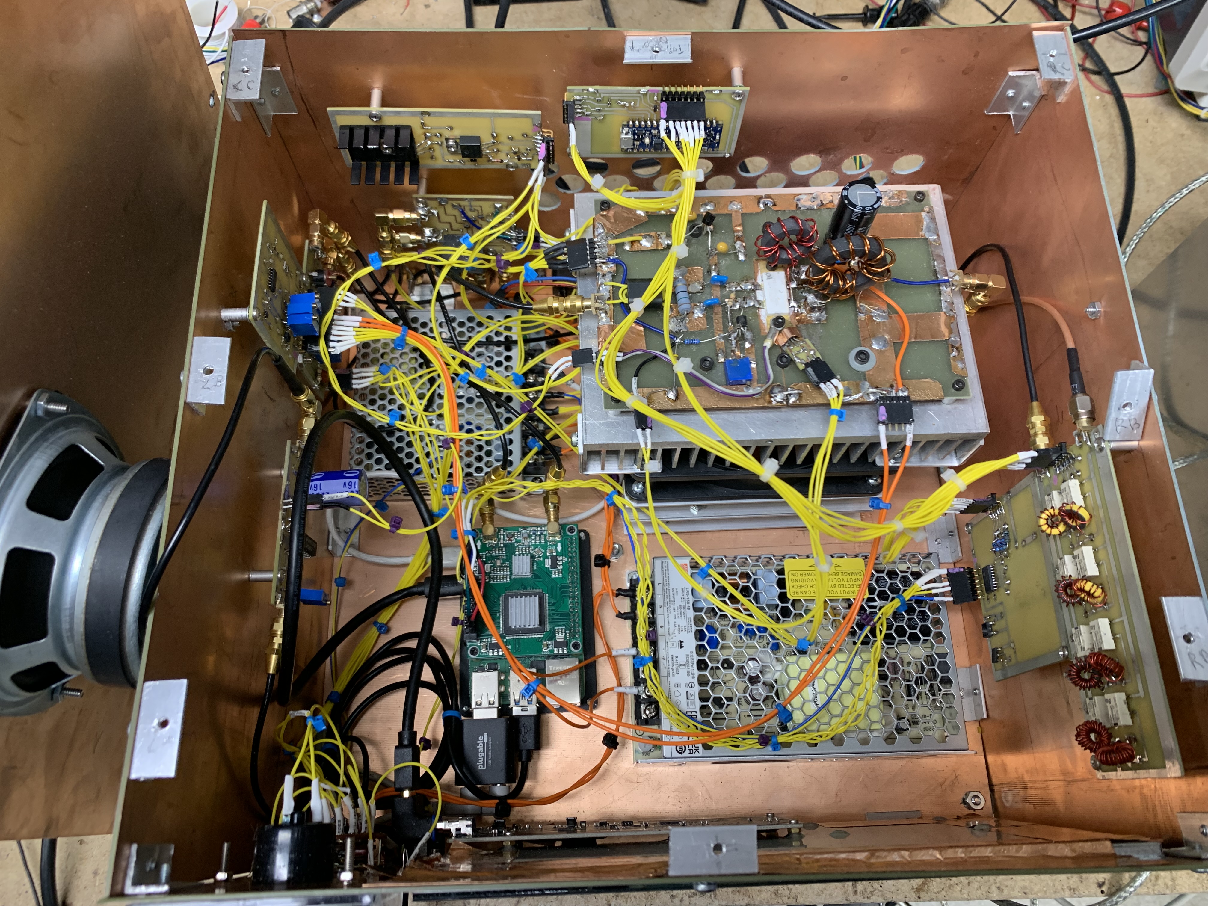
Inside of Transceiver. (click
for high resolution)
The details are as follows.
A) The power amplifier was from another
project, and is in the upper right of the photo mounted on the bottom plate.
It uses an LDMOS transistor pair MRFE6VP6300HR5. The transistors
are capable of 300 watts, but the Radioberry will only drive the amplifier
to 15 watts. The amplifier runs on 48 volts powered by a Meanwell
power supply shown in the lower right on the bottom plate. The transistors
are biased for bet 3rd order IMD which is 40 dB below the two tones.
The bias current is ~ 500 mA per transistor, so a fan is necessary to keep
the transistors cool. The Power Amplifier has about 30 dB gain so
the 15 mw from the Radioberry yields 15 watts output on 80m through 17m.
The output is about half that on 15m, 12m, and 10m.
LDMOS Power Amplifier.
B) The Radioberry/ RaspberryPi
is on the bottom plate just to the left of the 48 volt supply.
C) Just to the left of the power
amplifier, on the bottom plate, is another Meanwell supply that supplies
+5 volts and +12 volts.
D) A proportional fan controller
is shown on the back panel on the upper right. The T /R switch is
right below it, and the Arduino Linear Amplifier Interface are just to
the right of it.
Proportional Fan Controller.
The fan is only on when transmitting and stays on for about 5 seconds after transmitt goes off. The Thermistor is mounted on the transistor flange.
The T/R relay schematic is shown below.
T/ R Relay Schematic.
Mounted on the left side panel is the Audio Amplifier, the Measure Board and the Forward / Reflected Power circuit. The Measure Board measures transistor temperature, PA voltage, and PA curent. The Forward / Reflected Power Board measures Peak forward power.
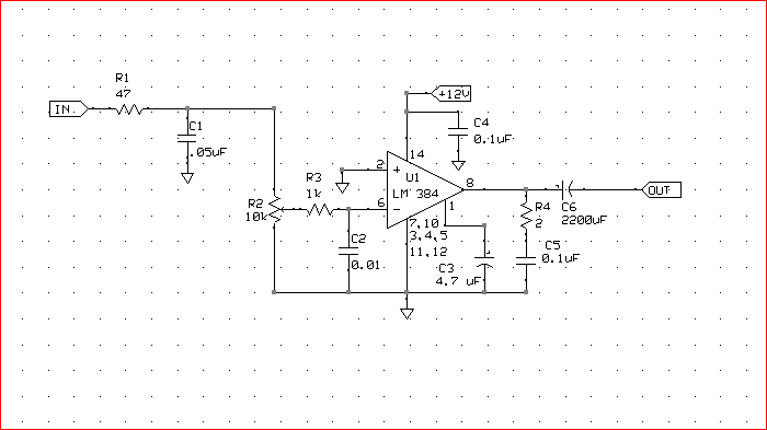
Audio Amplifier.
Measure Board.
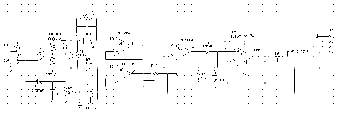
Forward / Reflected Power Bridge.
The Radioberry uses the N2ADR I2C interface to select Low Pass Filters as a function of band. The I2C interface board is shown below.

Low Pass Filter Interface Board.
The interface board connects to the Low Pass Filter board and the External Linear Amplifier board so that the low pass filters in both the Radioberry and the External Linear Amplifier follow the Radioberry band changes. The external amplifier board uses an Arduino Nano Every processor to generate the BCD code for the external amplifier band selection. The Arduino code can be viewed HERE
Low Pass Filter Board.
External Linear Amplifier Interface Board.
PiHPSDR is a very powerfull software package that runs
the Radioberry. Exploration of the functions just takes some time
poking around. Below are some of the options. Each tab has
more options such as a 3-band and 10-band equalizer for both transmit and
receive, a wide choice of filters on both SSB and CW, and many more just
to name a few.
PiHPSDR Radioberry Main Menu.
INTERESTING: My friend, Allen, K0ARK, used
Google Gemini Advance to create a podcast of the above HTML file.
Google Gemini is an artificial intelligence application. You can
listent to the podcast HERE.