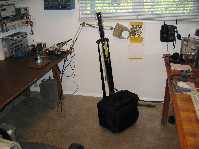
 A...
A...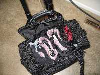 B...
B...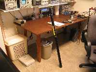 C...
C...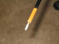 D...
D...
Small HF rigs make it possible to carry a complete station on an airplane. Photos A and B show the travel case packed complete with transceiver, power supply, Clear Speech speaker, antenna analyser, and antennas. MFJ makes a telescoping mast (part number MFJ 1910) that extends to 33 feet and collapses to about 48 inches and weighs about 3 pounds. This pole is made out of an insulating material much like phenolic. The mast is shown in the collapsed position attached to the travel case handle in photo A and by itself in photo C. I pushed a piece of #14 wire into the small section of the telescoping mast until it was tightly wedged. I cut it off so that it extended out the insertion end about 1/4 inch. I then soldered a female, cylindrical electrical diconnect terminal to the protruding end of the #14 wire as shown in photo D. I drilled a hole in the rubber end of the mast that is on the large end. The rubber peice may be removed by unscrewing the base ring. Be careful to hold the mast horizontally so all of the sections don't fall out. I then took about 35 feet of # 14 Flexweve wire and soldered a male disconnect connector to one end. I threaded the wire through the retainer ring and the hole in the rubber end and reattached the retainer ring. I telescoped the mast, pulling the Flexweve wire through until the mast was fully extended. I cut off the Flexweve with about an inch protruding from the bottom and soldered on another male connector. An 18.3 uH coil was constructed as shown in photos M and N. This coil was wound on a 3" OD, thin-wall, polycarbonate cylinder. The cylinder was scored in a lathe so that the coil has 16 turns in 2 inches. The measured Q of the unloaded coil is 345. A cheap, locking 12 foot tape measure was modified by cutting off the tab and screwing a male connector on to the end. The male connector is the right size to be tapped with a 4-40 tap, so that it can be secured to the end of the tape measure. Photo J shows this connection, as well as the current balun. The balun was an absolute must. My measurements made no sense without it. The balun consists of 14 turns of RG-58 on an FT240-43 core. Photos E through G show the extended mast outside a second story window. Photo H shows the arrangement inside the room, and photo I shows the base anchored to a chair. The chair must be very heavy, especially if there is any wind outside. Photos K and L show the tape measure counterpoise. Photos M and N show the loading coil for 40 meters. The coil can be shorted and a shorter wire threaded through the mast for use on the higher frequency bands. Finally, photo O shows the rig used in the 40 meter test.
Figures P and Q show the free space comparison between the portable antenna and a dipole using #14 copper wire. P is the dipole and Q is the portable. As you can see the difference in gain is only 0.58 db. Figure R shows what you might get in a hotel on the 15th floor. Don't you love that low angle of 13 degrees! The analysis was done using EZNEC by Row Lewallen.
I used an MFJ-259B antenna analyzer to tune the antenna. It can be resonated (zero reactance) between about 5 and 10 MHz with the 12 foot tape fully extended to fully retracted. About six feet of tape is used for 40 meters. The actual length will vary with the location of the antenna. On the air tests show between 5 and 10 db difference between my home station using a 40 meter kit on a Cushcraft A4-S up about 40 feet. Of course the building blocks radiation in one direction and that was the direction that I was talking. Further tests are needed and the results will be reported as the tests are done.
The mast can also be erected vertically as a quarter wave vertical by extending two radials in opposite directions, or it can be used to support the center of a full size inverted V. When used as a vertical, the antenna must be either mounted over a near perfect ground like sea water or elevate into the air at least 30 feet. The two radials will give a return current path, but they do not do much for lossy ground shielding.
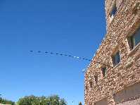 E...
E...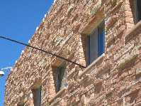 F...
F...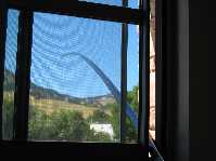 G...
G...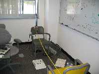 H...
H...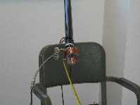 I...
I...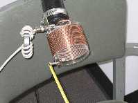 J...
J... K...
K... L...
L...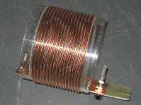 M...
M...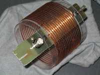 N...
N...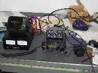 O
O
P
Q
R
I took my portable system to Oklahoma over a weekend and made some comparison tests with a flat top dipole strung in the trees at about 20 feet. Photos A, B, and C show the arrangement of the portable antenna. On 40 meters the difference was about 6 db with some reports indicating that the portable antenna was stronger.
I recently took a trip to Dedham, MA where I got to try out the portable setup from the third floor of a building. Photos A through G show the operation there. The building is an old mansion with wooden floors, so the counterpoise can rest on the floor as shown in B. I got good reports on 40 and 20 meters.